
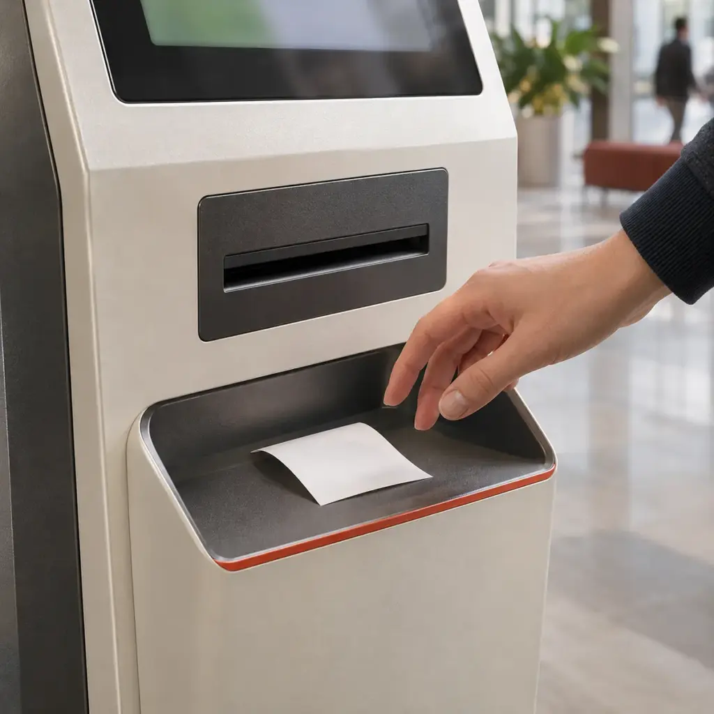
The receipt is readable. The cutter operates. The printer fits inside the cabinet. Yet the customer still has to reach into the opening, pull at the paper, or ask where the receipt has gone.
For kiosk printer integration, the handoff to the customer deserves its own engineering review. The printing assembly, enclosure opening and collection area form a connected arrangement. The way a person approaches that arrangement becomes part of its operating conditions.
This article follows one short part of the journey: from the cutter to the customer’s hand. The question is how the intended receipt reaches an accessible position, and what happens before and after it is taken.
Follow the Receipt Beyond the Mechanism
Consider an illustrative payment terminal with an 80mm thermal printing assembly behind its front panel. On the workbench, the paper leaves the mechanism freely. Once the panel is installed, it must pass through the equipment’s output arrangement before a customer can collect it.
The mechanism outline does not describe that complete route. An enclosure edge, guide, gap or change of direction may now influence where the leading edge goes. A layout that brings the printer close to the opening still needs to be checked with the actual paper and assembly.
After a receipt is fully severed, it is no longer pushed forward by the paper still inside the printer. Its next movement depends on the arrangement around it: for example, a separate transport system or a designed collection chute. Having an automatic cutter does not establish how a detached receipt reaches the outside of the cabinet.
This distinction is useful early in a project. Identify the position where printing and cutting happen, the opening through the front panel, and the place where the receipt is intended to wait. They may be close together, but they perform different jobs.
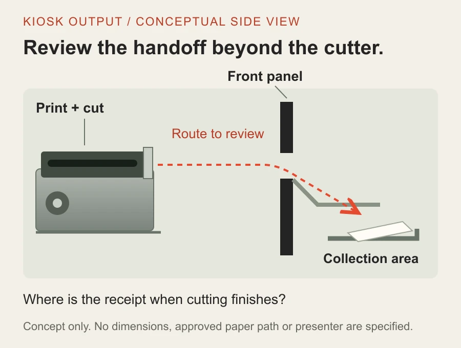
Conceptual output arrangement. The line marks the route to review, not an approved paper path. No mounting dimensions, clearances or presenter mechanism are specified.
The Opening and the Pickup Position Are Different
Paper can emerge through a slot without ending up in a convenient place to grasp. Review how much of the receipt is accessible, where a customer’s fingers can reach, and whether the paper remains in the intended collection area after separation.
An enclosure detail that looks adequate from the front may be less suitable from the side. The relationship between the printer outlet, the inner face of the panel and any collection surface belongs in the review. Paper curl, receipt length and the intended installation orientation can affect the behavior that needs to be evaluated.
There is no universal slot height or guide angle to copy into every cabinet. Review the selected printing assembly’s integration guidance and the actual enclosure. The longest and shortest intended printouts are more useful inputs than a generic picture of a printer inside a kiosk.
Our printer module space and loading guide looks at the wider enclosure problem. Here, the focus remains on what happens at the output end.
The Customer Can Reach the Paper Before the Job Is Finished
A person may see the first part of a receipt and assume it is ready. If the paper is exposed while printing continues, the equipment needs to account for that interaction. A “please wait” message can communicate the sequence, but the physical arrangement determines whether the customer can already grasp the paper.
A presenter is an additional paper-handling assembly that can control when the printed document is offered to the user. Sanei Electric’s presenter explanation identifies preventing ticket removal during printing as one of its functions. It also describes automatic collection of untaken tickets for the configurations discussed there.
Those functions should be agreed for the selected assembly and its control arrangement. A cutter separates paper; a presenter manages its delivery. Specifying one does not establish that the other is included.
The useful project question is when the customer should gain access to the receipt. In one application, paper may be exposed as it prints. In another, the document may need to be completed and separated before presentation. That decision affects the surrounding mechanical arrangement and operating sequence.
Decide Where the Untaken Receipt Goes
The output cycle does not always end with immediate collection. A customer may walk away, leave part of a transaction’s output behind, or request another receipt. Describe what the equipment should do in those circumstances before agreeing on an output arrangement.
For a collection tray or chute, consider where an untaken receipt rests and whether it interferes with the next one. For a presenter, establish how paper presence is detected, what initiates the next operation, and whether the selected configuration supports retraction. These are requirements to discuss with the supplier, rather than features to infer from the presence of an output slot.
Hengstler’s technical guidance on kiosk presenters explains that a designed chute can sometimes serve an application without a presenter. It also notes that loop-forming presenters need space for the paper loop, while retraction arrangements need somewhere to collect rejected documents. The relevant space depends on the chosen design and document length.
Adding paper handling therefore changes the installation review. The printer body’s dimensions alone do not describe the space needed for the entire output process or for removing collected paper during service.
Check the Sequence in the Enclosure
Use representative receipts with the proposed assembly and front panel. Observe the leading edge as it approaches the opening, the position of the receipt when cutting finishes, and its final pickup position. Include the intended operating orientation and the relevant range of document lengths.
Then review the next cycle: what happens if the first receipt remains, how the equipment responds to a detected output problem, and how an operator gains access for recovery. The selected product’s handling instructions should define the recovery procedure. A successful print on an open bench is a useful starting point; the enclosure evaluation addresses the actual handoff.
Agree on the Printing Assembly and the Surrounding Equipment
The Uright UR347C is an 80mm thermal printer mechanism with an integrated automatic cutter. Its standard supply does not include a control board. The mechanism and cutter provide part of an embedded printing assembly; the terminal’s output route and customer pickup arrangement must also be addressed in the project.
When discussing a kiosk printer mechanism, explain which parts already exist and which parts you need supplied. A printer mechanism, controller, paper holder, presenter, collection tray and enclosure may belong to different parts of the equipment. Establishing that scope makes the proposal easier to assess.
You do not need to choose every component before contacting us. Send a photo or side-view sketch showing the intended printer position and front-panel opening, together with a receipt sample. Explain whether customers can reach the paper during printing and what should happen if they leave it behind.
We can review the printing requirements with you and clarify which functions belong in the proposed supply and which need coordination with the rest of the equipment. Contact us by email or WhatsApp with the information you already have.