

An automatic cutter specification can contain three very different numbers: the time for one cutting operation, the permitted cutting frequency, and a rated number of cuts. Each describes a separate part of the operating requirement.
For example, the Uright UR347C mechanism lists an approximate cutter cycle time of 0.5 seconds, a maximum cutting frequency of 30 cuts per minute, and a cutter life of 1.5 million cuts. Reading the cycle time alone would miss an important scheduling constraint.
This article explains how to read those metrics together when specifying a receipt printer or integrating a mechanism. The published UR347C values provide a numerical example; the scheduling example is a calculation, not a recorded endurance or timing test.
Three Metrics, Three Different Questions
Cutting time describes an operation. A cycle-time figure gives the stated duration of the cutting operation under its specified conditions. The technical definition should establish the start and completion points. The delay between an application’s request and a finished receipt can also include data processing, printing and feeding.
Cutting frequency describes repetition. A maximum frequency specifies an allowable repetition rate for the stated operating conditions. The cycle-time figure alone does not establish the permitted frequency or authorize bursts of back-to-back cuts. Use the mechanism’s documented repetition requirements when designing the schedule.
Cutter life describes endurance. A rated cut count is an endurance specification associated with the relevant evaluation conditions. It does not, by itself, predict the calendar service life of a printer in every installation. Paper, cutting configuration and the operating conditions behind the rating belong in the assessment.
Why a 0.5-Second Cycle Does Not Establish the Repetition Rate
Dividing one minute by a cycle-time figure only produces a theoretical count of operations occupying that amount of time. It leaves out the separately specified repetition limit and the rest of the printing workflow.
For the UR347C’s published 30 cuts/min figure, an evenly spaced schedule gives:
60 seconds / 30 cuts = 2 seconds per cut interval
This is the start-to-start interval for an evenly spaced 30-cuts/min schedule.
The approximately 0.5-second cutter cycle and this calculated interval describe different quantities.
If one operation occupies approximately 0.5 seconds within that two-second interval, about 1.5 seconds remains in the example. That remainder is simply unallocated time in this calculation. It is not a specified cooling delay, a universal controller setting, or permission to place other actions anywhere within it. Actual sequencing follows the mechanism and system requirements.
A practical schedule must also account for the paper reaching a suitable cutting position and the cutter reaching its documented completion state. Printing speed, feeding behavior and the application’s job pattern therefore matter alongside the cutter specifications.
Review both sustained operation and the expected peak arrival pattern. A daily average can conceal several jobs arriving close together. The controller may need to queue work and return an appropriate status while completing the permitted sequence. Buffering changes when a job is processed; it does not increase the mechanism’s rated capability.
For more on the relationship between host commands, motion and operating feedback, see our thermal printer controller board guide.
Reading a Rated Life of 1.5 Million Cuts
When evaluating thermal printer cutter life, begin with the conditions attached to the endurance number. Ask which paper, cutting configuration, environment and acceptance criteria were used, and whether the figure describes the cutter assembly or a broader system evaluation.
This is a normal part of reading manufacturer specifications. For example, the Star TSP100 hardware manual associates its cutter-life statement with a paper-thickness range and recommended thermal paper. Those conditions describe the Star product; the corresponding conditions for a Uright configuration need to be discussed against its own specification.
For workload planning, count cutting operations rather than sales transactions. A workflow that prints and cuts a customer receipt, a merchant copy and a separate coupon generates three cutting operations. Reprints and other separately cut documents also belong in the workload record where they are used.
Dividing a rated cut count by an assumed daily workload can be useful for understanding scale. The result remains a count-based planning calculation. It does not incorporate every cause of wear, contamination, service intervention or a different operating environment, and should not be presented as a field-life forecast.
The UR-3390 receipt printer also lists a cutter life of 1.5 million cuts. A shared endurance number does not establish that two products have the same mechanism, paper limits or repetition requirements. Compare the complete specifications for the actual configuration being ordered.
Paper and Receipt Handling Are Part of the Cutting Conditions
Paper selection should include the permitted thickness and material as well as width and roll fit. A cutter intended for specified thermal paper should not automatically be treated as suitable for adhesive-backed stock, film or another material. Discuss such requirements before selecting the assembly.
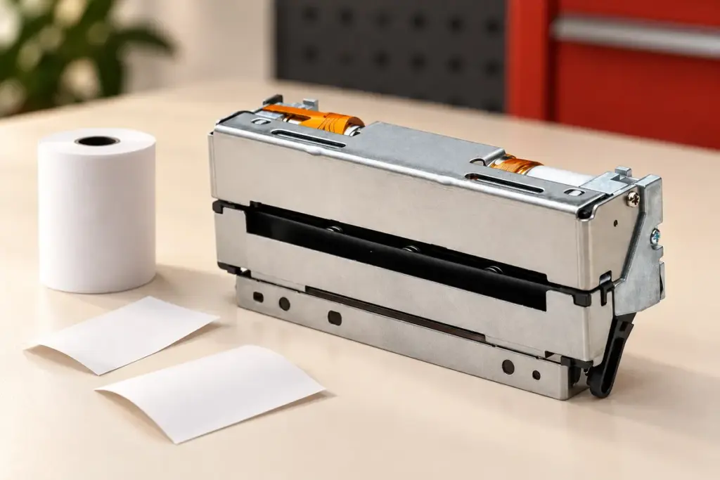
AI-generated editorial illustration based on the UR347C product photograph. Paper and receipt strips are staged for illustration.
Receipt length and the available output path need attention too. The UR347C lists a minimum cutting pitch of 10 mm. That is a mechanism specification to evaluate together with feed-to-cut positioning, print layout and the installed paper path; it does not automatically define the minimum finished receipt length for every host product.
Staff or customers should be able to collect the output using the intended method. Pulling or obstructing paper while it is being presented and cut can interfere with operation. Star’s manual also identifies interference during ejection as a potential cause of feeding or cutting problems. Evaluate the exit clearance, paper accumulation and collection arrangement in the actual installation.
Where multiple cutting modes are supported, record the required mode for the assessment. Its effect on the finished receipt and any corresponding endurance conditions should be defined for that product. Mode selection alone does not replace checking paper and duty requirements.
Define Completion and Recovery Before Evaluating a Sample
A host application’s cut request and a completed mechanical operation are different events. Establish which signal or controller status confirms completion, how a timeout is reported, and what happens to queued work if the cutter does not reach the expected position.
The UR347C lists cutter-home-position detection. How the host controller uses that signal, including fault reporting and recovery, belongs to the system implementation. Recovery should follow the documented method for the installed product and should not assume repeated automatic retries will clear an unresolved obstruction.
For a sample evaluation, record the paper, ordinary receipt lengths, short-document cases and the expected sustained and peak cutting workload. Observe cut quality, paper presentation, completion feedback and the response to supported fault conditions. Agree on acceptance criteria with the supplier; these are suggested evaluation items, not results already demonstrated by the article.
Information for a cutter-workload discussion
Printer or mechanism model; paper specification and source; normal and short receipt lengths; required cutting mode; sustained and peak cut demand; output collection arrangement; host control and recovery requirements.
Include your quantity and delivery destination when requesting a configuration or quotation.
For a complete receipt printer, discuss the UR-3390 with your POS and counter requirements. For mechanism integration or CAPD347-compatible replacement sourcing, review the UR347C and share the installed equipment details. You can explore equipment integration and mechanism replacement, or contact Uright Tech by email or WhatsApp.