

A short receipt prints normally. A longer job introduces a broad dark graphic, and the output changes: perhaps the density varies, printing pauses, or the printer restarts. The application is sending a valid job, so where should the discussion begin?
These observations can make the thermal printer power supply worth reviewing, but they do not establish the cause by themselves. The actual print job, the equipment’s power arrangement and its control behavior need to be considered together.
Follow one illustrative receipt through the process: sparse text, a dense graphic, then fine text again. The aim is to understand what that job asks of the printing system and what information helps a supplier assess it.
Look Along the Receipt, One Printed Row at a Time
A line thermal printhead contains a row of individually controlled heating elements across the paper. As the paper advances, successive printed rows build the image. The physical size of a logo alone does not describe the demand: its pattern determines how many elements need to be energized along each row.
Sparse text contains gaps. A broad solid area can require many elements across the head to print in the same row. A large outline drawing may have a different pattern again. This is why a short text receipt is a limited representation of an application that regularly prints filled logos or other dense graphics.
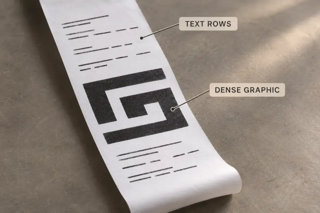
Illustrative print job, not an actual printer test. The marks represent different image patterns; they do not specify current, demonstrate a fault or compare model performance.
The controller determines how the requested row is delivered to the head. In a suitable design, print division can energize groups of elements at different times. ROHM explains print division as a way to reduce simultaneous current demand and voltage drop within the head. The grouping and timing must follow the selected head’s requirements.
This also connects power delivery to the available printing schedule. The system has to fit data handling, permitted heating operations and paper movement into its supported operating pattern. A printer’s maximum speed figure does not establish how every dense job will be scheduled. Our controller-board article discusses that coordination more broadly.
Read the Supply Rating in the Context of the Job
A voltage printed on an adapter identifies one requirement. A current rating identifies another. Neither tells the complete story of what happens when a particular print pattern is executed through the installed system.
Peak Demand and Sustained Demand Answer Different Questions
Thermal printing involves controlled heating intervals. In its standard printing conditions guidance, ROHM describes current consumption during printing as an instantaneous maximum dependent on the operating conditions. It also distinguishes the effective current requirement and notes that cable capacity must be considered separately.
For an equipment review, keep those conditions attached to any quoted figure. A printhead peak-current entry is not automatically the continuous output rating to request from an external adapter. Conversely, a modest average consumption figure does not establish that the complete arrangement can support the demands of a particular print cycle.
The motor, control electronics and cutter, where fitted, also belong in the system’s power budget. Whether particular loads overlap depends on the implementation and sequence. Adding unrelated maximum figures together, or looking at the printhead alone, can give an incomplete picture of the real requirement.
Voltage at the Adapter and Voltage Delivered to the Load
The relevant operating conditions apply at the components being supplied. Cables, connectors, switching circuitry and the return path are part of the delivery arrangement. Voltage can be lost along a current-carrying path, so the adapter’s label cannot establish the voltage available at the head during a loaded printing interval.
For an embedded assembly, the equipment designer needs to review the specified supply range, current demands and delivery path together. For a complete desktop printer, begin with the manufacturer’s specified power arrangement for that exact configuration. A matching plug shape or nominal voltage alone does not establish that another supply is suitable.
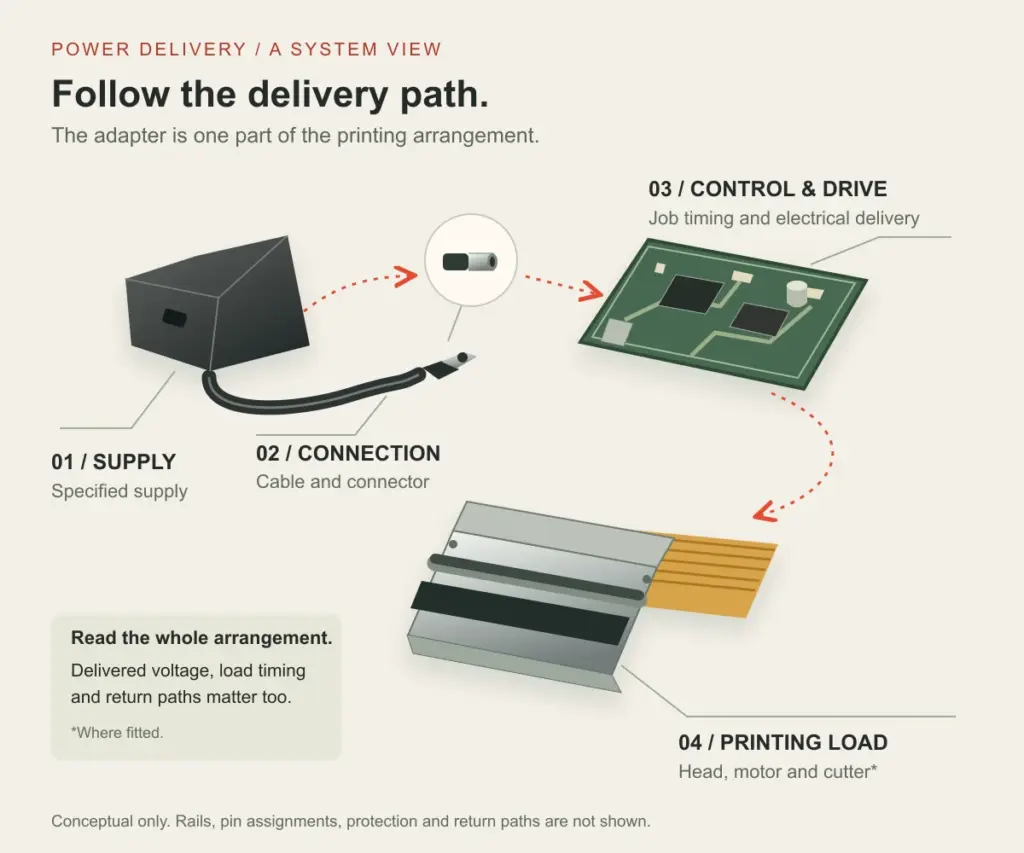
Conceptual component relationship. The highlighted route is not a wiring diagram, pin assignment or instruction for connecting a power supply. Actual rails, protection and return paths depend on the equipment.
A bare mechanism can require separate logic and printing-drive supplies through its specified interface. That is different from the external DC input of a finished printer. Identify which part of the system a voltage specification describes before using it in an enquiry.
Locate the Change in the Printing Sequence
Return to the illustrative receipt. Does the reported behavior begin as the dense section starts, after several receipts, or when a cutter operates? Does the fine text after the graphic look different from the text before it? Recording the point in the sequence gives the review a useful reference.
The timing can guide an investigation without proving a diagnosis. A pause can reflect the control strategy, while a reset or density change may require investigation of power delivery, temperature handling, configuration or another condition. Treat these as observations to explain, rather than a reason to change several settings at once.
For a supplier-led review, preserve the original file and operating setup. Record the selected speed and darkness settings, the existing supply identification, and whether the job is isolated or repeated. Where practical, a video showing the whole job and any indicator change can help relate the output to the sequence.
Do not substitute an arbitrary higher-current adapter or increase the voltage as a general remedy. Any proposed supply must match the complete equipment’s electrical and connector requirements. Electrical measurements inside an assembly should be planned by personnel equipped to interpret them using the relevant documentation.
Discuss the Complete Arrangement, Including What Already Works
A printer that handles the required workload reliably is useful context too. Explain which files work, which operating pattern produces the reported change, and what differed between the two. A controlled comparison makes the discussion more productive than replacing the printer, paper, supply and settings together.
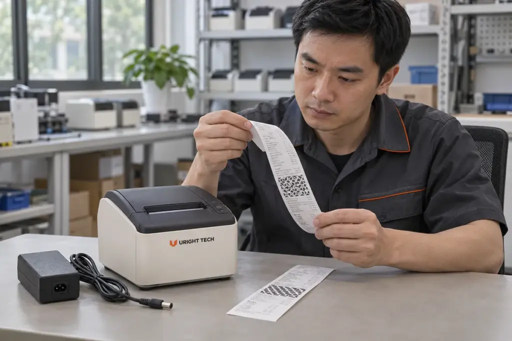
Editorial engineering illustration, not a Uright laboratory photograph or reported customer test. No electrical measurement or model-specific performance result is shown.
For complete-printer projects such as the Uright UR-3390 receipt printer, discuss the required print content and operating pattern alongside the selected printer configuration and supplied power arrangement. For an embedded mechanism project, include the existing controller and equipment supply information as well.
You do not need to calculate the head’s energization schedule before contacting us. Send the printer or mechanism model, a representative print file, a photo of the current power-supply identification, and a short description of when the behavior occurs. If you are planning a new installation, explain the intended sequence and the power arrangement already available.
We can review those requirements with you and clarify the printing configuration and technical information needed next. Contact us by email or WhatsApp with the material you already have.