
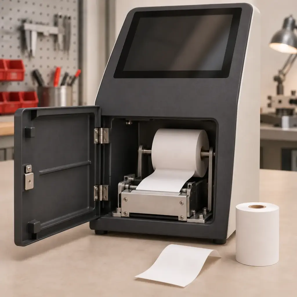
A search for a 2-inch thermal printer module often starts with a simple requirement: the equipment needs to print on a narrow roll of paper. That is a useful starting point, but it does not describe the space the complete printing arrangement needs inside the enclosure.
The mechanism may fit on a drawing while the paper roll, loading movement or receipt outlet does not. This article concentrates on that mechanical integration problem. You do not need to settle every specification before discussing a project; a print sample and a photo of the intended installation can make the first conversation much more useful.
First, Separate Paper Width from Printing Width
Treat “2-inch” as a starting search description, not an exact mounting or media specification. Ask for the actual paper width and effective printing width in millimetres. The width class alone does not establish whether the printed content will fit.
For example, the Uright UR48A mechanism uses 58 mm paper and provides a 48 mm effective printing width. Its listed body dimensions are 69.2 × 28.3 × 31.7 mm. These are three different pieces of information: the paper it accepts, the area it can print, and the size of the mechanism itself.
A receipt layout that uses the available width of a different printer may therefore need adjustment. A label also needs room for the required text and barcode layout within the actual printable area. Send the intended output rather than choosing a mechanism from the width label alone. We can review which parts of the layout are essential and which can be changed.
The Space That Is Missing from the Mechanism Outline
A mechanism outline drawing describes a component. The host equipment must also accommodate the consumable, the route it follows, and the movements needed to load and service it. These spaces can overlap when the equipment is opened, but they still need to be available.
The Roll Needs Its Own Envelope
Paper width tells you how wide the web is. It does not tell you the outer diameter of the roll, the core size or how the roll will be supported. A larger roll may reduce replacement frequency, but its effect on the enclosure and loading method must be considered together.
Include the selected holder or spindle in the layout. Check how the roll is retained and how a replacement reaches that position. A roll that fits once assembled may still be difficult to exchange through a small service opening. If the paper supply is separate from a mechanism-only product, the complete roll capacity is a host-equipment design question; it cannot be inferred from the mechanism’s paper width.
The Paper Path Connects the Components
Trace the route from the roll to the printing position and then to the point where the user collects the output. A cover, bracket or cable can occupy a space that looks empty in the mechanism drawing. The route also needs to match the loading arrangement of the selected product.
The UR48A, for instance, has a detachable platen and a specified 90-degree vertical paper-feed arrangement. That information belongs in the mechanical review. It does not supply a universal clearance or bend-radius rule for every installation. Use the selected product’s drawings and integration guidance to assess the actual route.
Loading Is a Movement, Not a Static Dimension
Consider how the operator opens the hatch, releases or removes the required part, inserts the roll, guides the paper and closes the assembly. A bracket just outside the mechanism outline may obstruct one of those movements. Access to a release lever or platen can matter as much as space for the new roll.
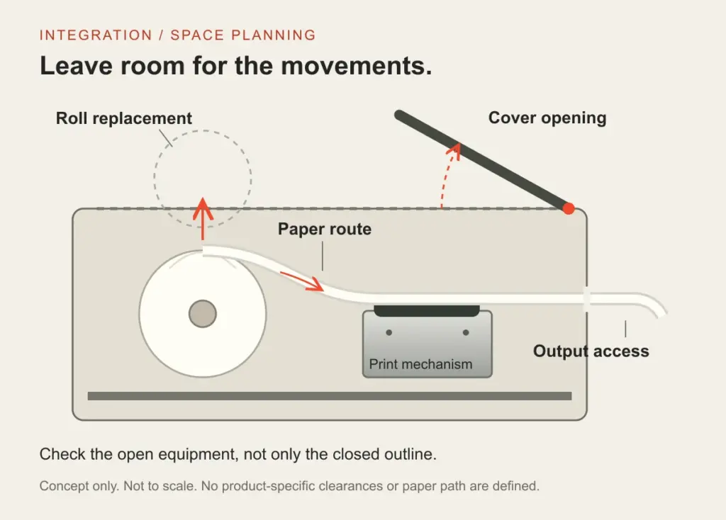
Conceptual space-planning illustration. It is not a product drawing, an approved paper path or a clearance specification. Actual layout and loading movements depend on the selected mechanism and host equipment.
Imagine a terminal placed below a fixed shelf. Its closed enclosure may fit comfortably, but a top-opening paper compartment may not have enough room to open in that installed position. Moving the same terminal onto a bench would hide the problem. This is an illustrative design situation, not a reported Uright customer installation.
Review access with the equipment in its intended location. Where practical, a simple enclosure mock-up with the proposed roll and loading sequence can reveal an obstruction before the housing is finalized. Exact allowances should come from the actual assembly, rather than an arbitrary clearance added to every side of a component.
Plan What Happens After Printing
For receipts, consider where the paper emerges, how the user reaches it and where an uncollected receipt can rest. Check the relationship between the mechanism’s output and the enclosure opening. If a cutter is required, select a configuration that supports it and assess the corresponding paper presentation. The mechanism-only UR48A does not include a cutter.
Labels introduce another possible movement: separating the printed label from its backing. A label-peeling arrangement and a liner-rewinding arrangement need to be considered alongside roll loading and output access. Printing a label and presenting it for removal are separate parts of the workflow.
The UR561P label printer module illustrates a different supply configuration: its standard assembly includes a control board, label peeling and liner rewinding, with a supported paper-width range of 30–62 mm. It is not interchangeable with a bare receipt mechanism simply because both deal with relatively narrow media. These examples explain the integration questions; they are not an automatic model recommendation for your project.
Decide What the Supplier Is Being Asked to Provide
The phrase “thermal printing module” does not, on its own, define the supplied assembly. Identify which parts are already available in the host equipment and which need to be provided: the mechanism, roll holder, control board, cutter, label handling and enclosure can belong to different parts of a project.
A mechanism without a controller is not a complete host interface. If your equipment already has a working printing system, share the existing model and assembly photos before selecting a replacement. If it is a new design, explain what the host needs to send and what the finished output should look like. Our controller-board article explains command compatibility and mechanism control in more depth.
The practical aim is to agree on a suitable printing arrangement and a clear supply scope. A smaller mechanism is not automatically the best answer if it makes loading difficult; a more complete module is not automatically necessary when the equipment already provides the required functions.
Start with the Application, Not a Finished Specification
You do not need to arrive with a chosen model or a complete engineering checklist. Send a photograph of the intended installation, a sample printout, or a short description of the task. If you have an existing mechanism, include its model label and a view of how it is mounted.
We can then discuss the next details that matter: whether the layout fits, where paper can be loaded, how the output will be collected, and what components are required. Some requirements may be adjustable; others may mean a different configuration is needed. Those decisions are easier to make from the actual application than from a single width or speed figure.
Explore our thermal printer mechanisms and modules or equipment integration applications. To discuss your project, send what you already have by email or WhatsApp.