
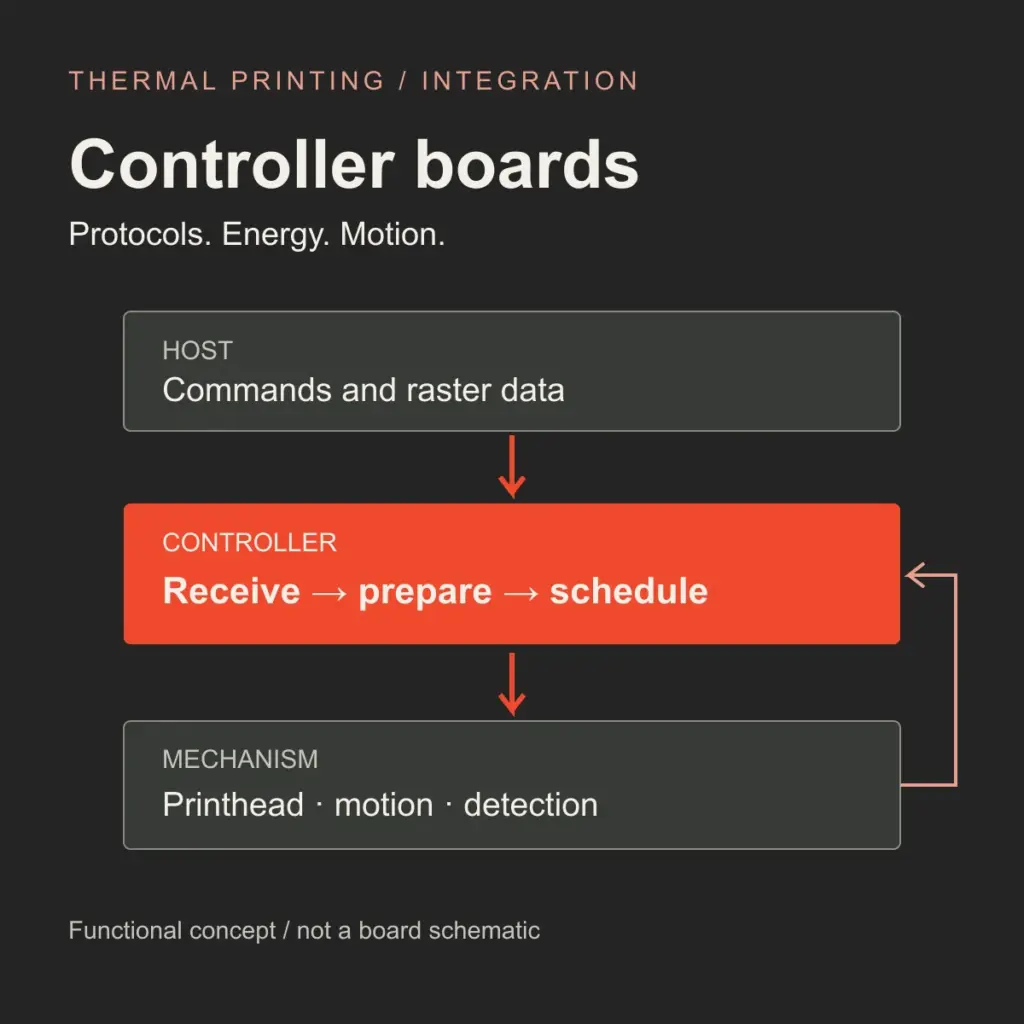
A thermal printer controller board connects a host application’s print request to the electrical and mechanical actions that put an image on paper. Its responsibilities can include receiving commands, preparing raster data, scheduling printhead energy, controlling motion and reporting operating conditions.
Protocol compatibility and mechanism matching must both be evaluated. A short text receipt exercises only a small part of the system. Continuous graphics, temperature changes, paper loading and interrupted jobs place different demands on the same hardware and firmware.
This article focuses on the relationship between command processing and mechanism-specific control in direct thermal printing. It describes engineering considerations; the supported functions and limits of a particular board must come from its documentation and validation.
Separate the Connection, Command Language and Mechanism Signals
The word “protocol” often covers several different requirements in an enquiry. Identify each layer separately.
| Layer | What needs agreement |
|---|---|
| Host connection and transport | Supported USB mode, serial electrical interface and communication settings, or the specified network or Bluetooth data service |
| Printer command language | Implemented commands, parameters, character encoding, graphics formats, status responses and mode selection |
| Mechanism interface | Pin assignment, logic levels, printhead timing, drive circuitry, motor requirements and available detector signals |
USB, a UART connection, RS-232 and Ethernet describe different connection or transport arrangements. UART signals at logic levels require the appropriate electrical interface; they should not be assumed interchangeable with RS-232. For any selected connection, the host and controller also need an agreed way to send data and receive status.
ESC/POS, TSPL/TSPL2, CPCL and ZPL are examples of command languages used in thermal-printing systems. They are implemented by particular firmware, sometimes with selectable emulation modes. A bare mechanism does not acquire these capabilities from its connector. Epson’s ESC/POS reference, TSC’s printer documentation and Zebra’s CPCL guide illustrate distinct command systems and implementations.
“ESC/POS compatible” therefore needs a defined scope. Test the actual application’s text, code pages, images, barcodes, feed and cut requests, and status handling. Receiving bytes successfully is one checkpoint; interpreting the job correctly is another.
From a Print Command to a Scheduled Raster Row
A controller that accepts formatted commands may generate character and barcode images, position them, and store raster rows for printing. In another design, the host may perform more of that rendering and send prepared image data. Buffering and flow control must suit the selected arrangement, particularly when the host sends data faster than the mechanism can print.
At the printhead, a common interface uses serial image data and a clock, a latch operation, and strobe signals that select heating intervals. ROHM explains this DI/CLK/LAT/STB arrangement. The applicable head documentation determines signal polarity, ordering, timing and drive limits.
The controller must turn these operations into a schedule that remains coordinated with paper motion. That schedule also depends on how the head is divided into heating groups and how much time each row requires.
Matching Heat to the Head, Paper and Workload
Heating Energy Depends on the Electrical Conditions
For an idealized resistive heating element, a useful first relationship is:
E(dot) ≈ V(heater)² × t(on) / R(dot)
E: energy delivered to one resistive heating element
V: voltage across that element
t: energized time
R: element resistance
Simplified resistive relationship. Actual drive design must account for the waveform, losses, thermal behavior and component limits.
This explains why the same pulse duration can deliver different energy when the voltage at the head changes. The adapter’s printed voltage is not a measurement of the voltage present at the heating elements during a loaded print cycle. Wiring and switching losses also matter.
An implementation needs the specified head resistance information, permitted energy and pulse conditions, supply characteristics and suitable paper. This relationship explains the dependency; it does not supply a universal pulse width or a complete thermal model.
Temperature Feedback and Thermal History Address Different Conditions
A head thermistor provides temperature feedback at its sensing location. It does not directly measure the instantaneous temperature of every heating element. A cold start and a head warmed by sustained printing can therefore require different drive treatment.
ROHM’s standard printing conditions discuss recording pulse width in relation to temperature and printing conditions. Where supported by the head and control design, thermal-history handling also accounts for recent energization patterns. Kyocera authors describe external and head-integrated approaches in their thermal printhead performance paper.
Temperature compensation and history processing should be assessed as specific implemented functions. A temperature sensor alone does not establish that a board includes a particular history-control algorithm.
Dense Rows Change the Power and Timing Budget
A sparse text row and a row containing many active dots can place different instantaneous demands on the supply. Head grouping and print division allow an appropriate design to distribute energization within the head’s specified limits. ROHM describes print division as a way to reduce simultaneous current demand and internal voltage drop.
The grouping decision also affects scheduling: heating more groups sequentially consumes time. The chosen speed, head timing, available supply and required image quality must be evaluated together. A review job should include dense graphics followed by fine text, rather than relying only on a short text print.
Coordinate Heating with Paper Motion
For a selected raster feed pitch and steady media speed, the nominal time between printed rows follows a simple kinematic relationship:
Nominal row period = raster feed pitch / media speed
Illustrative example:
0.125 mm / 200 mm/s = 0.000625 s = 625 µs per row
This is a scheduling-budget example, not a head heating time or an operating rating for a Uright product.
A speed requirement creates a row-scheduling constraint. Data transfer, applicable heating groups and motion must be arranged within the supported pipeline; some operations can overlap where the head and mechanism permit it.
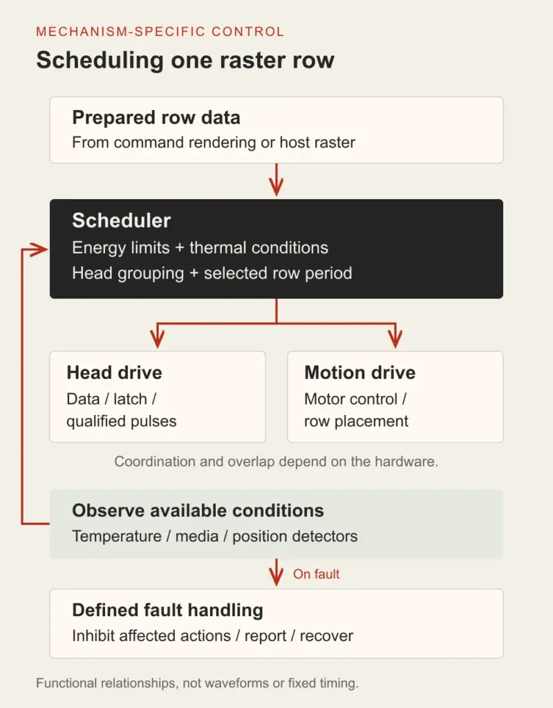
Conceptual scheduling diagram. Blocks are not electrical waveforms and do not specify pulse widths, polarity or motor phase timing. Actual overlap and ordering follow the mechanism and printhead documentation.
Motor phase sequences, current requirements, feed distance and acceleration behavior belong to the mechanism match. A change in head grouping or available heating time can require a corresponding review of the print schedule and speed strategy. Start-up, pauses and restarts also need evaluation; they are not the same operating condition as steady movement. A mechanism-specific control profile should identify the head’s data order and grouping, permitted drive conditions, motor phases, feed-distance conversion and detector logic. These details belong in the board-and-firmware match.
Reliable paper transport additionally depends on the platen, loading, paper path, supply drag and suitable media. The controller can coordinate motion and respond to available feedback, while the mechanical installation determines whether paper can move as intended. Issuing motor steps alone does not prove actual paper travel or establish slip detection.
Define Fault Handling and Job Status
A design review should distinguish data accepted, job executing, and the completion state actually observable by the system. The host needs documented meanings for the status it receives, including what happens to buffered work after a stop or restart.
For supported detectors, define the response to paper end, an open platen or cover, and abnormal head temperature. Where a cutter is fitted, include home-position confirmation, completion timeout and an explicit fault-recovery policy. Repeatedly retrying an unresolved mechanical fault should not be an assumed recovery strategy.
Overtemperature and power sequencing require the protection specified for the selected components. ROHM’s operating precautions discuss temperature monitoring, abnormal-condition shutdown and supply sequencing. An ordinary firmware polling loop does not by itself demonstrate all required fault protection.
Paper-end detection establishes the state of that detector. Reliable jam or stall reporting requires an appropriate sensing and inference design; the presence of a paper sensor alone is not evidence of comprehensive jam detection.
Validate the Combination, Then Define the Supply
A useful evaluation records the board and firmware, mechanism, supply, media, host path and print files. Compare cold and warmed operation, sparse and dense content, sustained jobs and controlled recovery from supported stop conditions. Record print position and density, code readability, supply behavior and status reporting against agreed acceptance criteria.
These are proposed review conditions, not reported test results or a claim that every controller implements the functions discussed above.
For a concrete supply distinction, the Uright UR48A is provided as a mechanism without a control/driver board or cutter. Its host equipment needs a suitable driving and control implementation. The UR561P label printer module includes a control board, label peeling and liner rewinding as standard. Each configuration has its own integration requirements.
When discussing a project, provide the mechanism model, available board or host hardware, required command language, sample print files, media, power arrangement, target workload and detector or cutter requirements. Explore equipment integration and mechanism replacement, or send the information by email or WhatsApp to discuss the supplied components and the validation needed.